House wires are mainly used for wiring domestic and commercial structures. They are capable of handling 85°C operating temperature since they are insulated with a flame retardant PVC compound (formulated and manufactured in-house).
Characteristics like these make Wires reliable, energy efficient and highly safe.
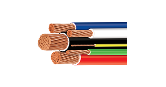
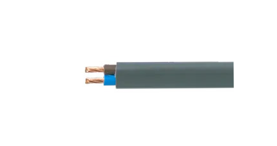
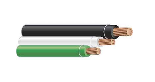
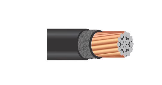
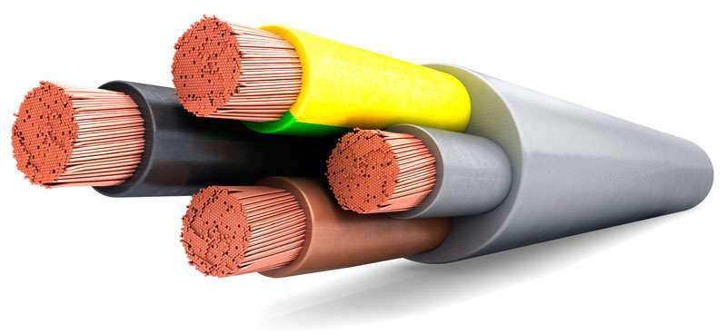
House Wire Catelogue
These cables are used mostly in residential buildings, commercial buildings, multiplexes, institutions and also in a wide variety of industries in machineries, tools, appliances and control panels.
IS: 694, BS: 6500, IEC 60227 and meeting customer requirements.
These wires work well even in adverse atmospheric conditions.
Copper – Solid, Stranded (Circular) or Flexible – Bare or Tinned
PVC-HR/FR/FRLS, Zero Halogen
| Conductor Area | No. & Size of Each Strand | Max. DC Resistance at 20°C | Insulation Thickness Nominal | Cable Dia App. | #Current Carrying Capacity | Conductor Area | No. & Size of Each Strand | Max. DC Resistance at 20°C | Insulation Thickness Nominal | Cable Dia App. | #Current Carrying Capacity |
|---|---|---|---|---|---|---|---|---|---|---|---|
| Sq. mm. | mm. | Ohm/Km. | mm. | mm. | Amp. | Sq. mm. | mm. | Ohm/Km. | mm. | mm. | Amp. |
| 0.50 | 16/0.20 | 39.00 | 0.60 | 2.10 | 5 | 35.00 | 276/0.40 | 0.554 | 1.20 | 9.9 | 110 |
| 0.75 | 24/0.20 | 26.00 | 0.60 | 2.30 | 8 | 50.00 | 396/0.40 | 0.386 | 1.40 | 11.8 | 145 |
| 1.00 | 32/0.20 | 19.50 | 0.60 | 2.60 | 13 | 70.00 | 556/0.40 | 0.272 | 1.40 | 13.5 | 215 |
| 1.50 | 30/0.25 | 13.30 | 0.70 | 2.90 | 17 | 95.00 | 756/0.40 | 0.206 | 1.60 | 15.5 | 260 |
| 2.50 | 50/0.25 | 7.98 | 0.80 | 3.60 | 24 | 120.00 | 954/0.40 | 0.161 | 1.60 | 17.1 | 305 |
| 4.00 | 56/0.30 | 4.95 | 0.80 | 4.00 | 30 | 150.00 | 1192/0.40 | 0.129 | 1.80 | 19.2 | 355 |
| 6.00 | 84/0.30 | 3.30 | 0.80 | 4.60 | 38 | 185.00 | 1472/0.40 | 0.106 | 2.00 | 21.3 | 415 |
| 10.00 | 80/0.40 | 1.91 | 1.00 | 6.10 | 52 | 240.00 | 1910/0.40 | 0.0801 | 2.20 | 24.2 | 500 |
| 16.00 | 126/0.40 | 1.21 | 1.00 | 7.10 | 70 | 300.00 | 2380/0.40 | 0.0641 | 2.40 | 26.7 | 585 |
| 25.00 | 196/0.40 | 0.78 | 1.20 | 8.70 | 88 | 400.00 | 3182/0.40 | 0.0486 | 2.60 | 30.7 | 640 |
100 mtrs Coils, Colours available Red, Yellow, Blue, Black, Grey & Green.
amra 1100V Grade Multi Strand Flexible Annealed Copper Conductor, PVC Insulated, PVC Sheathed Multi-Core Flexible Cables Conforming to IS: 694
| No. of Cores | "Area (Sq. mm) General Construction (No./Dia) Nom. Insu. Thickness (MM)" | "0.5 16/0.2 0.6" | "0.75 24/0.2 0.6" | "1.0 32/0.25 0.6" | "1.5 30/0.25 0.6" | "2.5 50/0.25 0.7" |
|---|---|---|---|---|---|---|
| 6 | Nom. Sheath Thickness MM | 0.90 | 1.00 | 1.00 | 1.00 | 1.10 |
| Maximum overall Dia. MM | 8.50 | 9.0 | 9.80 | 10.80 | 13.20 | |
| 7 | Nom. Sheath Thickness MM | 0.90 | 1.00 | 1.00 | 1.00 | 1.10 |
| Maximum overall Dia. MM | 8.50 | 9.0 | 9.80 | 10.80 | 13.20 | |
| 8 | Nom. Sheath Thickness MM | 1.00 | 1.00 | 1.00 | 1.10 | 1.20 |
| Maximum overall Dia. MM | 9.60 | 10.20 | 10.80 | 12.50 | 14.80 | |
| 10 | Nom. Sheath Thickness MM | 1.00 | 1.10 | 1.10 | 1.10 | 1.30 |
| Maximum overall Dia. MM | 10.80 | 11.80 | 12.80 | 13.90 | 17.30 | |
| 12 | Nom. Sheath Thickness MM | 1.00 | 1.10 | 1.10 | 1.10 | 1.30 |
| Maximum overall Dia. MM | 11.30 | 12.20 | 13.20 | 14.50 | 17.50 | |
| 14 | Nom. Sheath Thickness MM | 1.00 | 1.10 | 1.10 | 1.10 | 1.30 |
| Maximum overall Dia. MM | 12.10 | 12.80 | 13.80 | 15.50 | 18.50 | |
| 16 | Nom. Sheath Thickness MM | 1.10 | 1.20 | 1.20 | 1.20 | 1.40 |
| Maximum overall Dia. MM | 12.60 | 13.70 | 14.90 | 16.40 | 19.50 | |
| 19 | Nom. Sheath Thickness MM | 1.10 | 1.20 | 1.30 | 1.30 | 1.40 |
| Maximum overall Dia. MM | 13.20 | 14.40 | 16.00 | 17.40 | 21.20 | |
| 24 | Nom. Sheath Thickness MM | 1.20 | 1.30 | 1.40 | 1.40 | 1.50 |
| Maximum overall Dia. MM | 15.60 | 17.40 | 18.50 | 20.40 | 24.60 | |
| 25 | Nom. Sheath Thickness MM | 1.20 | 1.30 | 1.40 | 1.40 | 1.50 |
| Maximum overall Dia. MM | 15.60 | 17.40 | 18.50 | 20.40 | 24.60 | |
| Max. D.C. Conductor Resistance in ohm/Km. at 20°C. | 39.00 | 26.00 | 19.50 | 13.30 | 7.98 | |
| #Recommended Current Rating in AMP | 5 | 8 | 13 | 17 | 24 |
| Test | Function | Specification | Specified Values & Test | Obsd. Values |
|---|---|---|---|---|
| Critical Oxygen Index | To determine percentage of oxygen required for supporting combustion at room temperature of insulating material. | ASTM-D-2863 | Oxygen Index: minimum 29% Test sample 7 to 15 cm long by 6.5 + 0.5 mm wide & over 3 + 0.5 mm thick in a minimum concentration of oxygen and nitrogen mixture will just support candle like burning at room temperature. | More than 32 |
| Temp. Index | To determine at what temp. normal oxygen content of 21% in air will support combustion of insulating material. | ASTM-D-2863 | Temperature Index: minimum 250° C The aforesaid procedure at various temperatures & then extrapolating to 250° C. | Around 285° C |
| Smoke Density | To determine the visibility (light transmission) under fire of insulating material. | ASTM-D-2843 | Light Transmission: minimum 40% The test sample is exposed to flame to a 40 psi pressure for 4 minutes. The light absorption data and plotted on a graph as smoke density (%) versus time. | Around 45% |
| Acid Gas Generation | To ascertain the amount of hydrochloric acid gas evolved from PVC insulation of wire under fire conditions. | IEC 754-1 | Hydrochloric acid gas released: 20% max. 0.5-1 gram of the material from the wire insulation/sheath is burnt in a ceramic tube inside a tubular furnance at 800° C. The volume of corrosive gases (HCL) present in the combustion products are analyzed chemically. | Around 15% |
| Flammability test on group of cables | To determine flame propagation of wires in installed condition. | IEE-383 | In total 20 minutes of burning 8 ft. wire length samples with flame temp of app 1500° F. The burning of Cables should not go to the top. | Satisfactory |
| Flammability test | 1. To determine ignition resistance & flame propagation under specified conditions. | Swedish standard No. SS-424-17 | From test sample of 850mm length. The un-burnt portion shall be more than 300 mm from the top. | Satisfactory |
| 2. To determine ignition resistance & flame propagation under specified conditions. | IEC 332-1 | In the calculated time duration of burning the Cables wire sample of 600 mm 25 mm length the length of un- burnt portion to be min 50 mm from the top. | Satisfactory | |
| 3. To determine ignition resistance and flame propagation especially from bunch of wire under specified conditions. | IEC 332-2 | From test sample of 3.5 mtrs. length effected portion during burning shall not reach 2.5 mtrs. above from the bottom edge of the burner. | Satisfactory |
| Area (Nom.) Sq. | Number/size of Wire | Insulation Thickness Nominal | Sheath Thickness (Nom.) | Height 'H' (Maximum) | Width 'W' (Maximum) | Resistance at 20°C (Maximum) | Current carrying capacity at 40° |
|---|---|---|---|---|---|---|---|
| 1 | 32/0.2 | 0.6 | 0.9 | 4.5 | 9.9 | 19.5 | 13 |
| 1.5 | 30/0.25 | 0.6 | 0.9 | 4.8 | 10.8 | 13.3 | 17 |
| 2.5 | 50/0.25 | 0.7 | 1 | 5.7 | 12.9 | 7.98 | 24 |
| 4 | 56/0.3 | 0.8 | 1 | 6.2 | 14.5 | 4.95 | 30 |
| 6 | 84/0.3 | 0.8 | 1.1 | 7.2 | 16.4 | 3.3 | 38 |
| 10 | 80/0.4 | 1 | 1.4 | 9.2 | 21.5 | 1.91 | 52 |
| 16 | 126/0.4 | 1 | 1.4 | 10.3 | 24.7 | 1.21 | 70 |
| 25 | 196/0.4 | 1.2 | 2 | 13.1 | 30.9 | 0.78 | 88 |
| 35 | 276/0.4 | 1.2 | 2 | 14.3 | 34.6 | 0.554 | 110 |
| 50 | 396/0.4 | 1.4 | 2.2 | 15.5 | 40.5 | 0.386 | 145 |
| Frequency (MHz) | ATT (db/100m) max. | Ps Next (db) min. | PS ACR (db@100m) min. | PS Elfext (db@100m) min. | R.L. (db @ 100m) min. |
|---|---|---|---|---|---|
| 1 | 2 | 72.3 | 70.3 | 64.8 | 20 |
| 4 | 3.8 | 63.3 | 59.5 | 52.7 | 23 |
| 8 | 5.4 | 58.8 | 53.4 | 46.7 | 24.5 |
| 10 | 6 | 57.3 | 51.3 | 44.8 | 25 |
| 16 | 7.6 | 54.3 | 46.7 | 40.7 | 25 |
| 20 | 8.5 | 52.8 | 44.3 | 38.7 | 25 |
| 25 | 9.6 | 51.3 | 41.7 | 36.8 | 24.3 |
| 31.25 | 10.7 | 49.9 | 39.2 | 34.9 | 23.6 |
| 62.5 | 15.5 | 45.1 | 29.9 | 28.8 | 21.5 |
| 100 | 19.9 | 42.3 | 22.4 | 24.8 | 20.1 |
| 155 | 25.3 | 39.5 | 14.2 | 20.9 | 18.8 |
| 200 | 29.2 | 37.8 | 8.6 | 18.7 | 18 |
| 250 | 33 | 36.3 | 3.3 | 16.8 | 17.3 |
Tamra 1100V Grade Multi Strand Flexible Annealed Bare Copper Conductor, FR PVC Insulated and Unsheathed Single Core Flexible Cables Conforming to IS: 694
| Current Rating (Amps.) | ||||||
|---|---|---|---|---|---|---|
| Nominal Cross Sectional Area of the Conductor (Sq. mm) | Nos./Nominal Dia. Of Strand (Nos./mm) | Nominal Thickness of Insulation (mm) | Approx.Overall Dia Overall Dia (mm) | Conductor Resistance at 20° C Max. (Ohm/km) | 2 Wires In Conduit/ Trunking | 1 Phase # Clipped Directly to Surface or on Cable Tray |
| 0.75 | 24/.2 | 0.6 | 2.3 | 26 | 8 | 9 |
| 1 | 32/0.2 | 0.6 | 2.6 | 19.5 | 13 | 14 |
| 1.5 | 30/0.25 | 0.7 | 2.9 | 13.3 | 17 | 20 |
| 2.5 | 50/0.25 | 0.8 | 3.6 | 7.98 | 24 | 27 |
| 4 | 56/.3 | 0.8 | 4 | 4.95 | 30 | 33\ |
| 6 | 84/.3 | 0.8 | 4.6 | 3.3 | 38 | 42 |
Tamra 1100V Grade Multi Strand Flexible Annealed Bare Copper Conductor, FR PVC Insulated and Unsheathed Single Core Flexible Cables Conforming to IS: 694
| Conductor Area | No. & Size of Each Strand | Max. DC Resistance at 20°C | Insulation Thickness Nominal | Sheath Thickness Nominal | Overall Diameter Maximum | #Current Rating | ||||||
|---|---|---|---|---|---|---|---|---|---|---|---|---|
| Sq mm | mm | Ohm/km | mm | 2 Core mm | 3 Core mm | 4 Core mm | 5 Core mm | 2 Core mm | 3 Core mm | 4 Core mm | 5 Core mm | Amp |
| 0.5 | 16/0.2 | 39 | 0.6 | 0.9 | 0.9 | 0.9 | 0.9 | 6.2 | 6.6 | 7 | 7.5 | 5 |
| 0.75 | 24/0.2 | 26 | 0.6 | 0.9 | 0.9 | 0.9 | 0.9 | 6.6 | 6.9 | 7.4 | 8 | 8 |
| 1 | 32/0.2 | 19.5 | 0.6 | 0.9 | 0.9 | 0.9 | 1 | 7.1 | 7.3 | 8 | 8.9 | 13 |
| 1.5 | 30/0.25 | 13.3 | 0.6 | 0.9 | 0.9 | 1 | 1 | 7.5 | 8 | 9 | 9.7 | 17 |
| 2.5 | 50/0.25 | 7.98 | 0.7 | 1 | 1 | 1 | 1 | 9 | 9.4 | 10.4 | 11.3 | 24 |
| 4 | 56/0.3 | 4.95 | 0.8 | 1 | 1 | 1 | 1.1 | 10 | 10.6 | 11.8 | 13 | 30 |
| 6 | 84/0.30 | 3.3 | 0.8 | 1.1 | 1.2 | 1.2 | 11.2 | 12.3 | 13.6 | 38 | ||
| 10 | 80/0.40 | 1.91 | 1 | 1.3 | 1.4 | 1.4 | 14.8 | 17.6 | 16 | 52 | ||
| 16 | 126/0.40 | 1.21 | 1 | 1.4 | 1.4 | 1.4 | 17 | 18.2 | 20 | 70 | ||
| 25 | 196/0.40 | 0.78 | 1.2 | 1.4 | 1.5 | 1.6 | 20.3 | 21.9 | 24.5 | 88 | ||
| 35 | 276/0.40 | 0.554 | 1.2 | 1.6 | 1.6 | 1.7 | 23.1 | 24.8 | 27.5 | 110 | ||
| 70 | 556/0.40 | 0.272 | 1.4 | 2.2 | 2.2 | 2.2 | 32 | 34.2 | 37.8 | 215 | ||
| 95 | 756/0.40 | 0.206 | 1.6 | 2.4 | 2.4 | 2.4 | 35.8 | 38.3 | 42.2 | 260 | ||
| 120 | 954/0.40 | 0.161 | 1.6 | 2.5 | 2.5 | 2.5 | 39.6 | 42.4 | 46.9 | 305 | ||
| Current Rating (Amps.) | ||||||
|---|---|---|---|---|---|---|
| Nominal Cross Sectional Area of the Conductor (Sq. mm) | Nos./Nominal Dia. Of Strand (Nos./mm) | Nominal Thickness of Insulation (mm) | Approx.Overall Dia Overall Dia (mm) | Conductor Resistance at 20° C Max. (Ohm/km) | 2 Wires In Conduit/ Trunking | 1 Phase # Clipped Directly to Surface or on Cable Tray |
| 1 | 32/0.2 | 0.6 | 2.6 | 19.5 | 13 | 14 |
| 1.5 | 30/.25 | 0.7 | 2.9 | 13.3 | 17 | 20 |
| 2.5 | 50/.3 | 0.8 | 3.6 | 7.98 | 24 | 27 |
| 4 | 56/.3 | 0.8 | 4 | 4.95 | 30 | 33 |
| 6 | 84/.3 | 0.8 | 4.6 | 3.3 | 38 | 42 |
| Nominal Cross Sectional Area of the Conductor (Sq. mm) | Nos./Nominal Dia. Of Strand (Nos./mm) | Nominal Thickness of Insulation (mm) | Approx.Overall Dia Overall Dia (mm) | Conductor Resistance at 20° C Max. Ohm/km | Current Rating (Amps.) |
|---|---|---|---|---|---|
| 1 | 32/0.2 | 0.6 | 2.6 | 19.5 | 13 |
| 1.5 | 30/.25 | 0.7 | 2.9 | 13.3 | 17 |
| 2.5 | 50/.3 | 0.8 | 3.6 | 7.98 | 24 |
| 4 | 56/.3 | 0.8 | 4 | 4.95 | 30 |
| 6 | 84/.3 | 0.8 | 4.6 | 3.3 | 38 |
| Cable Type | RG 59 (Foam) | RG 6 (Foam) | RG 11 (Foam) |
|---|---|---|---|
| Conductor Diameter | 0.8 | 1.02 | 1.62 |
| Dia over dielectric | 3.55 | 4.57 | 7.1 |
| Dia over dielectric | 6 | 7 | 10 |
| Impedence | 75 | 75 | 75 |
| Capacitance | 53 | 53 | 53 |
| Velocity of propogation | 85 | 85 | 85 |
| Attenuation at 20° C (Db/100 yards) MHZ | RG 59 (Foam) | RG 6 (Foam) | RG 11 (Foam) |
|---|---|---|---|
| 100 | 6 | 5 | 3.5 |
| 200 | 11 | 9 | 6 |
| 300 | 15 | 12 | 8 |
| 500 | 20 | 16 | 11 |
| 800 | 27 | 21 | 15 |
| No. of Pair | 0.45 mm Dia. Over Insulation (mm) | Conductor Approx. Overall Dia (mm) | 0.50 mm Dia. Over Insulation (mm) | Conductor Approx. Overall Dia (mm) | 0.60 mm Dia. Over Insulation (mm) | Conductor Approx. Overall Dia (mm) | 0.70 mm Dia. Over Insulation (mm) | Conductor Approx. Overall Dia (mm) |
|---|---|---|---|---|---|---|---|---|
| 1 | 0.8 | 2.6 | 0.9 | 2.8 | 1 | 3 | 1.2 | 3.7 |
| 2 | 0.8 | 4 | 0.9 | 4.4 | 1 | 4.7 | 1.2 | 5.6 |
| 3 | 0.8 | 4.2 | 0.9 | 4.6 | 1 | 5 | 1.2 | 5.9 |
| 4 | 0.8 | 4.6 | 0.9 | 5 | 1 | 5.4 | 1.2 | 6.4 |
| 5 | 0.8 | 5 | 0.9 | 5.4 | 1 | 5.9 | 1.2 | 7 |
| 6 | 0.8 | 5.4 | 0.9 | 5.9 | 1 | 6.4 | 1.2 | 7.6 |
| 8 | 0.8 | 5.7 | 0.9 | 6.3 | 1 | 6.8 | 1.2 | 8.1 |
| 10 | 0.8 | 6.7 | 0.9 | 7.4 | 1 | 8 | 1.2 | 9.3 |
| 20 | 0.8 | 8.6 | 0.9 | 9.5 | 1 | 10.3 | 1.2 | 12 |
| 40 | 0.8 | 11.8 | 0.9 | 13 | 1 | 14.1 | 1.2 | 17 |
| 50 | 0.8 | 13.2 | 0.9 | 14.6 | 1 | 16 | 1.2 | 18.7 |
| Attenuation at Different Frequencies | |||
|---|---|---|---|
| 100 | 6 | 5 | 3.5 |
| 100 | 6 | 5 | 3.5 |
| 100 | 6 | 5 | 3.5 |
| 100 | 6 | 5 | 3.5 |
| 100 | 6 | 5 | 3.5 |